ΠTar Flying V

Building this bit of insanity for VirtCon 2021. The idea had been rattling around in my head for a bit, and I decided that the competition was a good opportunity to build it.
I decided to continue with the transforming feature from the last one, and the musical instrument theme from the first one, so here’s the ΠTar Flying V Cyberdeck.
It’s a 3d-printed deck based around the general outline of a Flying V electric guitar, folding from guitar mode to “crate-top” cyberdeck mode. The neck is made of 2020 Aluminum Extrusion (aluminum extrusion was one of the requirements of the competition). At the center of it all is a camera tripod ball joint, allowing one half of the guitar to rotate in two axes, moving it from guitar mode to crate-top mode.

Guitar Mode
Crate-Top Mode
It’s designed to be carried around like a guitar and play music through a belt-amp, and transformed quickly into a desktop unit.
Given that this site has more of a bent towards people designing and building, I thought I’d share a few elements and processes that I found useful or interesting rather than the normal simple promotional material.
Early Planning:
I did some simple sketches which I turned into early 3D models in my process.

They were helpful initial visualizations (even if I did start over from scratch on the models) but those weren’t what was the most helpful for me, planning wise.


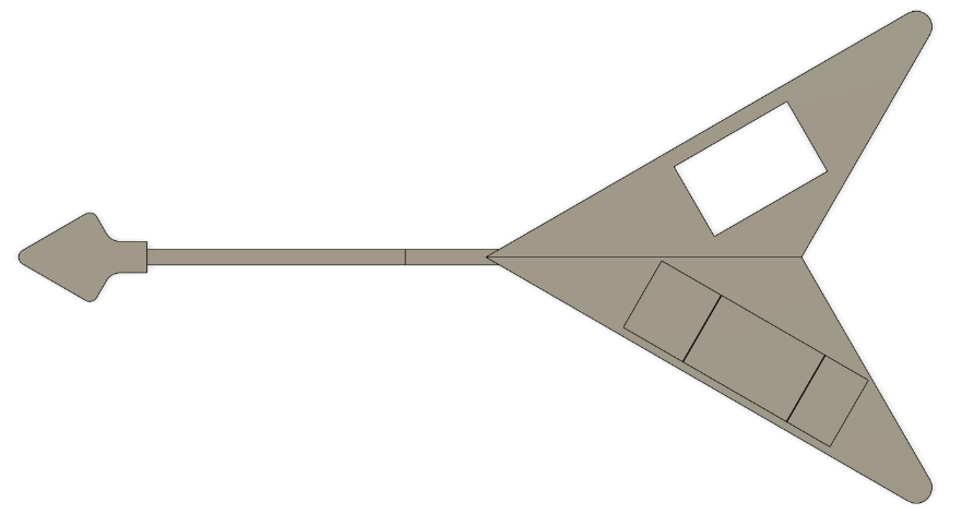
Enter kraft paper and a pencil. I used some measuring implements and parts to figure out the outline and angles of the design at full scale. I wanted it to look like a flying V electric guitar, but all the internal electronics had to fit. I did an initial estimated sketch at angles I thought would work, but then placed components on so I could determine what angles would give me the internal volume and shapes I needed.
Note: Since I realize how poorly they show up at this distance, I have since decided to upgrade to larger diameter pencils in my shop for this sort of work. Always trying to improve the workflow!

The Folding Neck:
The folding neck was about the easiest part of the build to accomplish. A quick parts search (online and in my hardware bins) led me to build something that was assembled shortly after I received the parts. It’s just a hinge, a stiffener, a screw with a handle to lock the stiffener in one position or another, and a couple of t-slot nuts, installed on a couple pieces of 2020 extrusion.

2020 Extrusion Interface:
I found a drawing of dimensions of 2020 extrusion and made sure to recreate it as a 3D model for two reasons:
This allowed me to show a bit more visibly in the model what was going on in the design and
I was able to offset from that outline to create parts that interlocked with the rail from the casing.
This allowed me to have the keyboard side of the case attach solidly to the rail and spread the forces across a larger area than just relying on the t-slot nuts to carry the force.
Modular Construction Process:
This project was designed and built on a very limited timeframe. I needed to get parts to the printer as soon as possible. Most prints were estimated to be overnight prints, though I might be able to get multiple prints done if I were off that day. One night I even made sure to manage to get one smaller print completed and then a larger print overnight, to buy myself time.
As part of the need to do this, and knowing that this was going to be a complex project, I designed and printed it in order of increasing complexity. The head of the guitar was first, as it was simple, and didn’t have any interdependence with the other 3D printed parts.
Then I designed the shell of the keyboard half and mirrored it to create the outline for the monitor half. Given the limitations of my 3D printer (and this being the largest thing I’ve ever built from 3D printed parts), I had to split it into sections that would fit on my printer. I then had to add the spaces for the attached components on that half, and start getting those out to the printer. When I finished the simplest component and got it onto the printer, I would try to finish the next simplest component and repeat. They weren’t entirely independent of one another, and I would at least have to get the matching mechanical interfaces built for the interfacing components on the preceding and proceeding parts before I could print either. The ball joint interfacing components were left for absolute last, but I did have to get the interfacing components designed for them to match up with the rest of the shells.
Once I finished designing the keyboard half, I had to go through a lot more complex designing on the monitor half while the keyboard half printed. The vast majority of the electronic hardware was in that half, and that required a lot of mounting components solidly to the shell and making close-fitting cut-outs for cables and a button to stick out of. Some of these parts took multiple attempts, but I got there, after I set my pride aside and printed the bare minimum to check fit on several items before reattempting printing entire components.
Lastly was the ball joint, which took a few tries to get all the measurements precisely lined up.


Interiors:
The interior of the keyboard section was also comparatively simple, as it was just mechanical connections and a couple mounts for the magnets that hold the folding keyboard on.
One of the insane parts was the monitor side of the casing.
I’d never attempted anything this complex, and remember, we only had a month to do this. Everything that was accessible from the outside needed a custom hole. Components such as the display, battery, and the raspberry pi itself all had to be securely mounted. Wires had to be able to physically interface and get to useful places. This took a while. Especially when I tried to add a power button to the Pisugar2 Pro, which was not intended to have a button external to the board.
The Ball Joint:
This part was a pain. I’m so glad I had made up some extra print time earlier in the project, as I ended up having to go through a few draft parts for this. The ball joint had to precisely connect with both sides of the casing and distribute the loads. I designed a rotational end-stop to constrain the motion of the ball joint… and the bolt broke straight through the plastic. I also ran into an issue where the heat set insert for the ball joint going into the monitor side came loose. Thankfully, the same solution worked for both. A 3D printing pen and some more of the plastic the case was made of!
It’s not pretty, but it worked. I also used some hot-glue to fixt the other side of the ball joint in place a bit (after that second photo).
Transformation:

After all that work, I finally got the thing to move the way I wanted it to.
https://www.youtube.com/watch?v=KYGC5xuiyds&ab_channel=Ralnarene
If you’d like more information, please visit my blog, here:
https://technomancers-sanctum.blog/cyberdecks/%cf%80tar-flying-v-cyberdeck/
There you can find the in-universe sales flyer that I made for the deck, and links to more posts where I covered the challenges of designing and building it in a month.