ZeroDays - 1st Place Design - The TTSD-3085

Archival Information: TTSD-3085
Product introduction letter, from CEO Cyber Buffalo Industries
Includes official production gallery along with employee build notes and logs.
<<<<<<<<<<<<<<<<<<<<<---------BEGIN-------->>>>>>>>>>>>>>>>>>>>>>>>
Hello [CUSTOMER] and thank you for your interest in Cyber Buffalo Industries’ [TTSD-3085], a tiny cyberdeck built for [30% efficiency and 85% chaos]! It brings us great pleasure to know that you are considering making a CBI product your own.
In order for you to better understand the [TTSD-3085], we have prepared some materials for you to look over. We hope this will help you make an informed decision on wether or not the [TTSD-3085] is right for you!
Enclosed you will find a product gallery, Teknical Specks, and a sneak peek into the private journal of the engineers that painstakingly and contractually brought the [TTSD-3085] to life.
From all of us at Cyber Buffalo Industries, we thank you and hope to make you part of the Cyber Buffalo family!
CEO, Cyber Buffalo Industries
<<<<<<<<<<<<<<<<<<<<<<---------END-------->>>>>>>>>>>>>>>>>>>>>>>>>
...........................................................................................................................
DEVELOPMENT JOURNAL...........................................................................
............................................................................................................
First conceived as a portable terminal and minimalist computer, this deck was created for the Cyberdeck.Cafe [ZERO DAYS CON], a small convention bringing together the cyberdeck community. The contest, build a deck with some kind of display based off of the Raspberry Pi Zero SBC.
When I first started to design for the contest, my sketches and ideas were way different than they are now. I thought about creating an all-in-one doomsday device with several add-on modules. I purchased a light sensor, a radio receiver and a GPS module thinking I would integrate these into the design. I also started researching Gozim and Kiwix, two offline wikipedia readers, as having offline wikipedia for when the internet crumbles into the hands of megacorporation control was also appealing.

My initial design was something that more resembled a Pokédex or Al’s handheld AI assistant Ziggy from the hit TV show [QUANTUM LEAP]. The one thing all the designs initially had in common is that they were handheld, had a screen at the top and some combination of buttons and keys at the bottom. I had some designs that I thought looked good and feasible, so I started to plan.
During the planning phase, I kept getting caught up on the keyboard. How does one make a keyboard? What kind of buttons (switches) can be used to make a keyboard, and how does one program that keyboard to make sure that everything works the way it is intended?
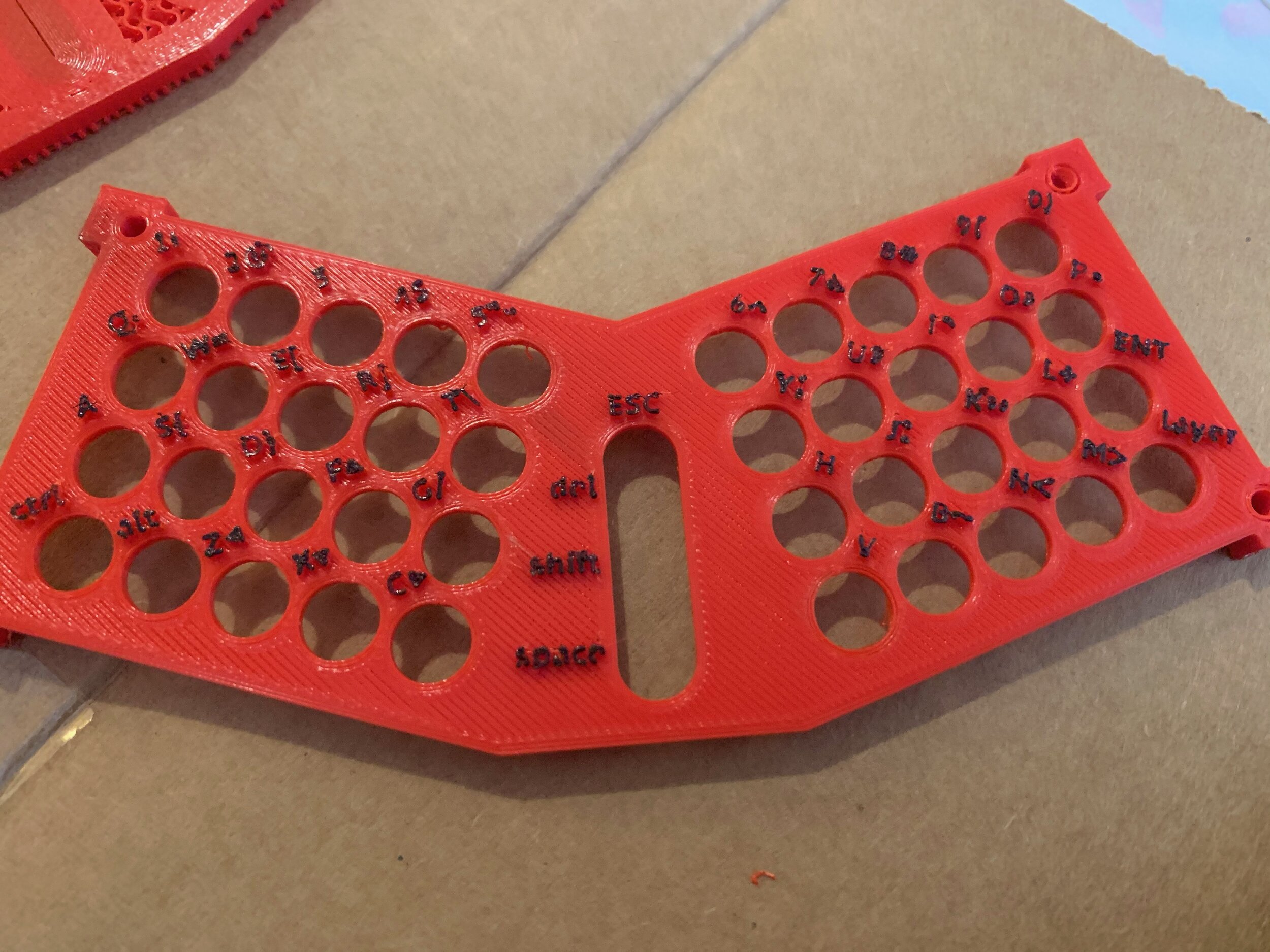
This led to more research which led to some simple sketches and then eventually, I had a plan in mind: 40 keys, 4x10, all laid out in a rectangle that would provide mostly everything I thought I would need to navigate linux and do simple text input.
I found some resources online that took the pain away from laying out a keyboard (www.keyboard-layout-editor.com & www.kbfirmware.com) and I started doing some mockups in illustrator, and it turns out I was missing some really important keys.
The keys ESC, DEL, SHIFT, SPACE and TAB were unaccounted for so I split the keyboard in two sections at an angle and threw a row up the center. This allowed me to the four center keys as those important 5 (SPACE and TAB share a key, shifted by the LAYER key in the bottom right-had position). And with those keys not occupying either of the two sides, it will (mostly) prevent accidental entry (hitting ESC at a less than opportune time would be frustrating and infuriating).

I finished the mockup in illustrator and set out to figure out how to make it a reality. Coming up with the shape, I thought, was going to be the most difficult part. It turns out that hand wiring a keyboard matrix takes a lot of time. Outside of that, figuring out what a keyboard matrix is was even more difficult for me.
I read guide after guide after guide, and they all said the same thing about rows and columns and diodes, so I decided to start small and soldered 4 tactile switches to a perf board and then figure it out from there.
Using kbfirmware.com, I built a 2x2 keyboard keyboard hex: A,S,Z,X. I think it took me about 3 days to get that working. I drew schematics so I knew what I had tried and what I hadn’t tried. It finally clicked when I realized what was going on when you pressed a button.

With the theory mostly under wraps, I just went for it. I took a perfboard and laid out the keys, giving myself a hole between each column of keys. Once the tact switches were soldered into place, I laid out the diodes and the traces for the columns and rows and soldered away. Each half of the keyboard took about 2~ hours of soldering.

To make the center row, I laid each side down on top of another piece of perfboard and then traced a shape that I liked. I scored the perfboard with a knife and then snapped it into a triangle. To connect the three together I put them in a bench vice and then soldered points from one board to the other.
A little piece of paperclip or copper wire would have been handy here but I didn’t think of it until after it was done. Then I wired up the center column, connected it to the adjacent rows and attached some kynex wire leads to the columns and rows, and temporarily connected it to a sparkfun pro-micro microcontroller.

After pushing the hex file to the microcontroller, I tested and not surprisingly it didn’t work, at least not the way I expected to. It was outputting random key presses, half the board didn’t work, it was utter chaos (85% in, fact!). My problem was with the software, though!
It was the first thing I checked because of the way it was malfunctioning. There exists an option on kbfirmware.com that I overlooked when I built the software the first time. It asks you if your diodes go row to column and column to row, and it defaults to the one I didn’t do.
After reattaching my button to put the pro-micro into write mode, the file was written, and the goddamned thing worked! Well like 95% of it did. I had to reflow a few traces and and fix a few shorts, but after 20 minutes of futzing around with it, the keyboard was fully functional.
It was at this point, which was about a week away from the deadline that I began considering the form factor. I had a few requirements that I wanted met.
I wanted the keyboard to support the screen
I wanted to the screen and pi stack to have a simple enclosure that wasn’t more than it needed to be.
Some form of repositionability
The first step was making sure I could figure out how to use the screen that I bought. Its an Adafruit 2.8” PiTFT + with resistive touch. . After some searching and reading the documentation I was able to get it setup on the pi and configured the output how I liked it (GUI, why not!).

This is probably the most boring part of the creation process. It was me with fusion 360 and a metric ruler, squinting under the light of my desk and ferociously scratching numbers on a pad so I wouldn’t forget them.

I like fusion 360 because it feels real. Starting with a 2D sketch makes the most sense to my brain when it comes to planning a 3d object.
After taking measurements of the pro-micro and the keyboard, I made a rendering of a keyboard housing that would accommodate both while also leaving enough room for wiring.
I also thought, with the geometric form factor that down the road, if I were to continue research and development of this, there could be enough room to house 1 or 2 Li-Po cells on the underside of the keyboard compartment.
I printed a test to check fit then turned my attention towards getting the screen positioned. It was nice to be able to hold the screen stack in place around the keyboard, it gave it a sense of place and I was able to translate that fusion.
The key to connecting the two was defining a hinge point that could extend off the back of the keyboard. This allows a small amount of modularity. I can upgrade the upright hinge post or the screen bezel (or both) and maintain the keyboard. I could also design an enclosure that holds a different SBC like a pi 3/4 or the like.

On the back of the screen bezel I decided to go with a honeycomb pattern. Besides looking cool, this allows for airflow and also it gives rudimentary access to the GPIO pins. One could theoretically hardwire into the back of the GPIO and then route those through the honeycomb to whatever board you were prototyping.

As I finished the screen I began thinking about a universal prototyping rail system, or some kind of mounting point that I would like to add if I wanted to bring some of those modules from earlier into the design. Bolting on equipment is absolutely something that I think fits with the theme and make of this device.
Everything is assembled with M2 and M3 screws. The keyboard uses (four) M2 nuts and bolts that go through the top plate, the pcb, the center enclosure and the bottom plate. The pro-micro is pressure fit into a slot on the underside of the enclosure. The hinge post attaches to the back of the keyboard enclosure through 2 sets of m3 nuts and bolts.
The top of the hinge uses 1 M3 nut and bolt. The screen 5 holes on the front. One of the holes is currently unused, It was added because there was a hole on the screen board in that position, and I figured if it wasn’t accessible maybe it could be used to poke an led through in the future.
Three of the holes go straight through the front, the screen board and the back. 1 of them just threads directly and tightly into the screen board itself. On the back of the screen through the honeycomb, 2 more screws are put into place securing the raspberry pi zero. A short micro-usb to micro-usb OTG cable connects the keyboard to the pi.

I left a small channel open on the front of the screen so the 4 GPIO buttons on the screen can easily be accessed. I didn’t have a need for them at the time, but after watching the GPIO programming tutorial during the Zero Days Con I got a few ideas that I will begin working on (it’s been added to the list).
For the color scheme, I had initially thought about beige. Who doesn’t like a good beige? My first computer, an Apple ][ clone by Zenith was beige and I loved it. I talked myself out of ordering more filament, I had a spool of black and red PLA, and I’ve always been fond of the Sony HitBit computers, so after some consideration I decided to go with that.
These were also the colors I was prototyping in and I had grown fond of them. Having decided on the final colors, I actually went back to the design and redesigned the way the top plate of the keyboard met with the enclosure.
I wanted something there to break up the sea of red that would be the top plate so shrunk the edges of the top plate and extended the sides of the enclosure, creating a claw of sorts that grabbed onto one another.

This was originally intended to be purely aesthetic but as I started to do it, I realize that I would be able to make the entire thing more stable and fit together better. In the future, if I were to print the keyboard again, I would consider putting in a few stand-offs somewhere in the center of the keyboard to be able to pull that down to the pcb with 2 screws from the underside, just to make sure everything sits flush.
To label the keys, I exported my original Illustrator layout as an SVG and imported it as a layer, then extruded the labels onto the top plate. After printing, I came back with an artists marker and painted them in.

I am VERY happy with the results, it feels like such a real thing an I’ve gotten a lot of pleasure (and burns, and cuts, and pulled hairs) from creating it. I’m currently trying to work out the method for creating the form factor of the keyboard into a PCB that can be offered to the community, as a few people had mentioned interest in a mini split keyboard like that.

I’m also currently making a new enclosure for a larger screen that doesn’t have much larger of a footprint. In the future I would like to figure out a hinge post that would facilitate folding the screen so it becomes parallel to the keyboard, for simpler travel.
So far my favorite way to use this is handheld, the keyboard layout offers great accessibility for quick thumb typing, and the range of the screen allows for it to be laid all the way back. In the end, it did become the handheld device I never knew I wanted. ..........................................................................................................................
////////END JOURNAL.................................................................................
...........................................................................................................
Come checkout everything Cyber Buffalo has to offer at http://www.cyberbuffaloindustries.com/